
Electrical integration#
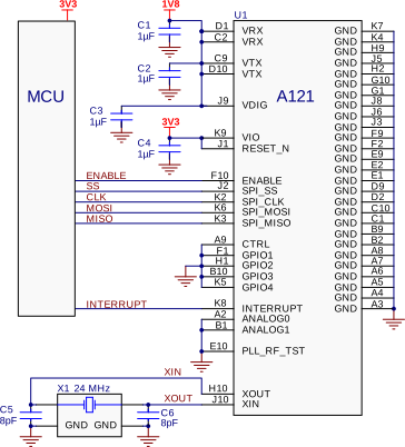
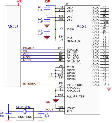
The A121 sensor contains the mmWave front-end, digital control logic, digitization of received signal and memory, all in one package. To integrate it in your application a 24 MHz crystal, a power supply, and a host MCU are required. The sensor works with both 3.3 and 1.8 V host interfaces as shown in Figure 33 and Figure 34.
Power#
The A121 radar sensor requires a 1.8 V input to the RX, TX, and VDIG power domains. The A121 VIO power domain can be powered by either 1.8 V or 3.3 V. For a 1.8 V interface, the VIO and RESET_N signals are connected to VDIG and therefore the C4 decoupling capacitor is optional. To avoid stressing the A121 and to optimize the current consumption, the VIO on A121 should be equal to the I/O voltage on the host MCU that controls it. The A121 current consumption when the ENABLE pin is low is <1 µA and therefore no power switch is required.
The A121 draws approximately 3 mA in the SLEEP state and approximately 75 mA in the MEASURE state. Thus when the sensor changes states, a load transient appears on the 1.8 V power domain. The power regulator and decoupling must be able to handle this without the output voltage dropping below the minimum operating supply voltage. For details regarding the power consumption of A121, refer to the A121 Datasheet.
SPI and I/O interfaces#
If the power to the A121 is switched off in between radar sweeps, it is important that the SPI interface as well as other I/O signals are pulled low during this time to avoid reverse leakage currents through the ESD diodes.
To ensure good signal integrity for the SPI bus, it is recommended to keep the SPI traces as short as possible with an adjacent ground plane. Place a ground via close to each signal via when changing layers to maintain a constant trace impedance. Impedance matching of the SPI bus is usually not needed as the trace lengths are electrically short for low drive strength configurations.
Electrical design checklist#
When designing the hardware schematics for the A121 sensor, the following checklist can be used to ensure a good design:
Does the selected crystal fulfill the load conditions according to the A121 Datasheet?
Have you connected all sensor ground pins to common ground?
For more information, see: