Loopback#
Loopback refers to the process of measuring the generated pulse electronically on the chip by routing it directly to the receiver, rather than transmitting the energy out into the air.
The easiest way to get familiar with the loopback measurement is through the Sparse IQ service
in the Exploration Tool.
The feature is enabled/disabled using the Sensor Configuration parameter
enable_loopback.
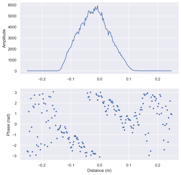
The following graph shows the measured amplitude and phase with loopback enabled.

Figure 16 Upper graph: Amplitude of loopback measurement. Lower graph: Phase of loopback measurement.#
As can be seen, the result looks like a regular measurement with amplitude and phase. The loopback measurement has the following key features:
#1 - The center of the envelope is located close to zero distance.
#2 - The phase pattern of a loopback measurement and a regular measurement are highly correlated. Phase pattern refers to the series of phase values measured over the defined distances points.
#3 - Timing variations originating from sensor-sensor variations has the same impact on loopback measurements and regular measurements. Timing variations refers to slight shifts of the measured envelope in the distance domain.
#4 - As no energy is transmitted into the air, the measurement is not effected by the surroundings and can be performed at any time.
The following sections illustrates how the loopback measurement is utilized to enhance the performance of the system.
Improved distance estimation#
Key features #3 and #4 are used in the distance detector to improve the distance accuracy over sensor individuals.
The distance detector estimate the distance to an object as the location of the peak amplitude in the measured envelope. Due to sensor-sensor variations and temperature effects, the timing of the measured envelope from two sensors with identical installation can differ slightly. Hence, variation in envelope timing translates into an error in the estimated distance.
As noted in key feature #3, the envelope timing variation also impacts the loopback measurement. The distance detector takes advantage of this correlation through the implementation of an offset error compensation. The compensation takes the location of the envelope peak amplitude of a loopback measurement as input and outputs an offset value, applied to the estimated distance.
Key feature #4 allows the compensation to be performed at any time, without any considerations to the sensors surroundings.
Phase jitter reduction#
Key features #2 and #4 can be used to reduce phase jitter of the measured points.
As stated in key feature #2, the phase of a regular measurement and a loopback measurement is highly correlated. This implies that the phase jitter of a regular measurement at any given time can be estimated through a loopback measurement, as the latter is not impacted by the sensor surroundings, according to key feature #4.
The distance detector takes advantage of this concept to achieve a more stable distance estimate when measuring close to the sensor, referred to as a close range measurement. For details, see the Distance Detector documentation.
The concept behind the close range measurement strategy is to first characterize the direct leakage and then coherently subtract it from the signal to isolate the signal component of interest. The phase jitter introduce unwanted residuals in the result after subtraction and makes the distance estimate less robust.
The distance detector is configured with a first subsweep containing a regular measurement, used for the distance estimation. It is followed by a second subsweep containing a single point with loopback enabled, used in the process of reducing the impact of the phase jitter.
The direct leakage is characterized by storing a snapshot of the complex values in the first subsweep. At the time of characterization, it is paired with the loopback measurement in the second subsweep, referred to as the loopback phase reference.
As the loopback measurement is not impacted by the sensor surroundings, any deviation in phase from the loopback phase reference is due to phase jitter. The difference is referred to as the instantaneous phase jitter.
Before performing the coherent subtraction, the argument of the complex samples of the characterized direct leakage are adjusted by the amount reflected by the instantaneous phase jitter, to mitigate the impact of the phase jitter.
The full procedure results in a vector with reduced residuals originating from the phase jitter and yields a more robust distance estimate.
Phase enhancement#
Key feature #2 and #4 are used to achieve phase coherent data in the distance domain.
Phase coherency in the distance domain enables coherent distance filtering, allowing for increased SNR through data processing. For details regarding distance filtering, see the see the Distance Detector documentation.
The first step of the phase enhancement process takes place during the sensor calibration where a loopback measurement is performed to quantify the phase pattern over a fixed distance interval. Next, the result from the calibration is applied to subsequent measurements, where the argument of the complex samples are adjusted according to the quantified phase pattern.
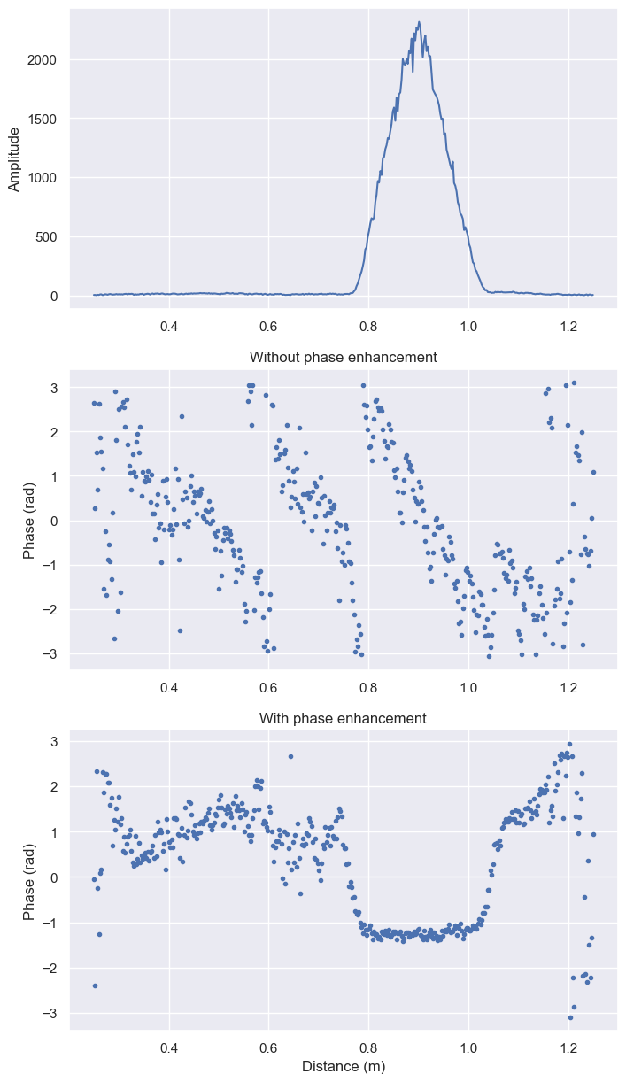
The following graph shows the phase and envelope of a measurement against a single target, with and without phase enhancement enabled.

Figure 17 Upper graph: Amplitude of measured sweep. Middle graph: Phase of measured sweep with phase enhancement disabled. Lower graph: Phase of measured sweep with phase enhancement enabled.#
The phase enhancement feature is implemented as a part of RSS and can be enabled/disabled through the API. The easiest way to get familiar with the feature is through Exploration Tool, where it can be enabled/disabled.
IQ imbalance compensation#
Key features #2 and #4 are used to achieve consistent envelope amplitude values in the distance domain.
The phase rotates at a distance point when an object moves within a small interval and corresponds to where in the interval the object is located. IQ imbalance causes oscillation in amplitude when the phase rotates. Amplitude oscillation will cause the center of gravity of a peak to shift and impair distance estimation. Compensating for the IQ imbalance will reduce the amplitude oscillation.
Loopback measurements are performed to quantify the IQ imbalance at all distance points in a small interval. The result is used to calculate compensation coefficients, one for each distance point in the interval. The complex samples from a distance point are adjusted by multiplication with the corresponding coefficients. The IQ-imbalance repeats outside the small interval so the same coefficients are reused for all distances.
Figures below show the phase rotation and resulting amplitude, with and without IQ imbalance compensation, for an object that moves within the interval. The left and right envelope corresponds to the same object but with different phase rotations.

Figure 18 Amplitude oscillates when the phase rotates over a distance without compensation.#

Figure 19 Amplitude does not oscillate when the phase rotates over a distance with compensation.#
The IQ imbalance compensation feature is implemented as a part of RSS and can be enabled/disabled through the API. The easiest way to get familiar with the feature is through Exploration Tool, where it can be enabled/disabled.