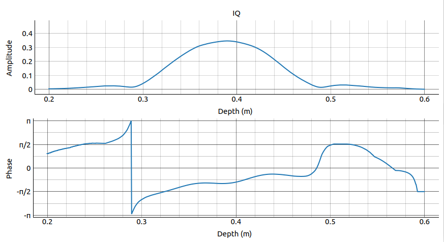
IQ#
The IQ service utilizes the phase-coherency of the Acconeer pulsed radar to produce stable In-phase and Quadrature (IQ) components, capable of detecting fine movement occurring in a target scene. Such micro-motions can be used in, for instance, presence detection in front of the sensor, detection of breathing rate and obstacle detection.

The In-phase and Quadrature components are represented as complex values in cartesian form, generating a complex set of \(N_D\) samples represented as \(x[d]\), where \(d\) is the delay sample index. Each complex value has an amplitude and a phase as in \(x[d] = A_de^{i\phi_d}\). A \(2\pi\) phase rotation of an IQ data point corresponds to a movement at the specific distance of \(\lambda/2 \approx 2.5\) mm, providing high relative spatial resolution.
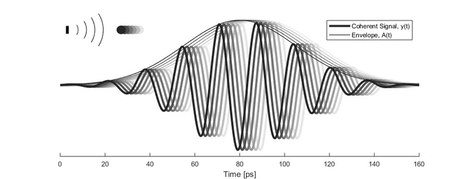
The cartesian data can be transformed to polar data providing phase and amplitude of the signal. Having the phase of the signal available makes it possible to perform more accurate measurements as compared to the Power bins and Envelope Services where only the amplitude is available. This is illustrated in Figure 65 where an object is moving towards the radar. The envelope of the signal only varies slightly when the object is moving, while the value of the coherent signal at a fixed time delay varies substantially. This change will be present in the phase of the data from the IQ Service.

Figure 65 Illustration of envelope and phase change of a received pulse for a reflection from a moving object, what is returned from the IQ Service is in cartesian form.#
Similarly to the Envelope service the amplitudes obtained through the IQ service provide a method for examining the reflectivity at different distances from the radar sensor. These two services are however differently optimized. The Envelope service is optimized for providing an accurate envelope estimate, while the IQ service is optimized for producing a phase-stable estimate. Thus, one should only use the IQ service if phase information is of importance.
For phase estimation in the vital sign use case and for object detection in the robot use case, Profile 2 and 3 are recommended. To get data good data from the IQ service with Profile 1, sampling mode B and a Hardware accelerated average samples (HWAAS) of at least 20.
The filtering of data in the IQ Service applies a low-pass filter in the range dimension. This leads to some filter edge effects in the first few centimeters of the sweep. For very short sweeps, approx. 3 cm for Profile 1 and approx 6 cm for Profile 2-5, these edge effects affects the magnitude and phase of the whole sweep. It is therefore recommended to add at least 3 cm to the sweep at each end for Profile 1, and 6 cm for Profile 2-5, to the region where the amplitude and phase should be estimated.
The IQ service can be configured with different pulse length profiles, see Profiles.
Detection of micro-motions using the IQ service in a target scene has many use cases, some of which are presented in Sleep breathing, Obstacle detection, and Phase tracking.
examples/a111/services/iq.py contains example code on how the IQ service can be used.
For further reading on the IQ service we refer to the IQ documentation on the Acconeer developer page.
Configuration parameters#
- class acconeer.exptool.a111.IQServiceConfig
- class SamplingMode(value)
- sampling_mode
- Default value: SamplingMode.A
- depth_lowpass_cutoff_ratio
Depth domain lowpass filter cutoff frequency ratio
The cutoff for the depth domain lowpass filter is specified as the ratio between the spatial frequency cutoff and the sample frequency. A ratio of zero ratio will configure the smoothest possible filter. A ratio of 0.5 (the Nyquist frequency) turns the filter off.
If unset, i.e., if not overridden, the ratio will be chosen automatically. The used ratio is returned in the session information (metadata) upon session setup (create).
Type: floatDefault value: None
- class PowerSaveMode(value)
- asynchronous_measurement
Enabling asynchronous measurements will result in a faster update rate but introduces a risk of interference between sensors.
Type: boolDefault value: True
- downsampling_factor
The range downsampling by an integer factor. A factor of 1 means no downsampling, thus sampling with the smallest possible depth interval. A factor 2 samples every other point, and so on. In Envelope and IQ, the finest interval is ~0.5 mm. In Power Bins, it is the same but then further downsampled in post-processing. In sparse, it is ~6 cm.
The downsampling is performed by skipping measurements in the sensor, and therefore gives lower memory usage, lower power consumption, and lower duty cycle.
In sparse, setting a too large factor might result in gaps in the data where moving objects “disappear” between sampling points.
In Envelope, IQ, and Power Bins, the factor must be 1, 2, or 4. In sparse, it must be at least 1. Setting a factor greater than 1 might affect the range end point and for IQ and Envelope, also the first point.
Type: intDefault value: 1
- gain
The receiver gain used in the sensor. If the gain is too low, objects may not be visible, or it may result in poor signal quality due to quantization errors. If the gain is too high, strong reflections may result in saturated data. We recommend not setting the gain higher than necessary due to signal quality reasons.
Must be between 0 and 1 inclusive, where 1 is the highest possible gain.
Note
When Sensor normalization is active, the change in the data due to changing gain is removed after normalization. Therefore, the data might seen unaffected by changes in the gain, except very high (receiver saturation) or very low (quantization error) gain.
Sensor normalization is not available for the Sparse service, but is enabled by default for the other services - Envelope, IQ, and Power Bins.
Type: floatDefault value: 0.5
- hw_accelerated_average_samples
Number of samples taken to obtain a single point in the data. These are averaged directly in the sensor hardware - no extra computations are done in the MCU.
The time needed to measure a sweep is roughly proportional to the HWAAS. Hence, if there’s a need to obtain a higher sweep rate, HWAAS could be decreased. Note that HWAAS does not affect the amount of data transmitted from the sensor over SPI.
Must be at least 1 and not greater than 63.
Type: intDefault value: 10
- maximize_signal_attenuation
When measuring in the direct leakage (around 0m), this setting can be enabled to minimize saturation in the receiver. We do not recommend using this setting under normal operation.
Type: boolDefault value: False
- noise_level_normalization
With the SW version 2 release, a sensor signal normalization functionality is activated by default for the Power Bins, Envelope, and IQ Service. This results in a more constant signal for different temperatures and sensors. The radar sweeps are normalized to have similar amplitude independent of sensor gain and hardware averaging, resulting in only minor visible effect in the sweeps when adjusting these parameters.
We recommend this setting especially for applications, where absolute radar amplitudes are important, such as when comparing to a previously recorded signal or to a fixed threshold.
More technically, the functionality is implemented to collect data when starting the service, but not transmitting pulses. This data is then used to determine the current sensitivity of receiving part of the radar by estimating the power level of the noise, which then is used to normalize the collected sweeps. In the most low-power systems, where a service is created to collect just a single short sweep before turning off, the sensor normalization can add a non-negligible part to the power consumption.
Please note, that due to the nature of Sparse data, the Sparse service does not support noise level normalization. Instead, normalization during processing is recommended, such as done in the Presence detector.
Type: boolDefault value: True
- power_save_mode
The power save mode configuration sets what state the sensor waits in between measurements in an active service. There are five power save modes. The modes differentiate in current dissipation and response latency, where the most current consuming mode Active gives fastest response and the least current consuming mode Off gives the slowest response. The absolute response time and also maximum update rate is determined by several factors besides the power save mode configuration.
In addition, the host capabilities in terms of SPI communication speed and processing speed also impact on the absolute response time. The power consumption of the system depends on the actual configuration of the application and it is recommended to test both maximum update rate and power consumption when the configuration is decided.
Power save mode
Current consumption
Response time
Off
Lowest
Longest
Hibernate
…
…
Sleep
…
…
Ready
…
…
Active
Highest
Shortest
Note
Hibernation has limited hardware support. It is not supported by the Raspberry Pi EVK:s and XM112.
Default value: PowerSaveMode.ACTIVE
- profile
The main configuration of all the services are the profiles, numbered 1 to 5. The difference between the profiles is the length of the radar pulse and the way the incoming pulse is sampled. Profiles with low numbers use short pulses while the higher profiles use longer pulses.
Profile 1 is recommended for:
measuring strong reflectors, to avoid saturation of the received signal
close range operation (<20 cm), due to the reduced direct leakage
Profile 2 and 3 are recommended for:
operation at intermediate distances, (20 cm to 1 m)
where a balance between SNR and depth resolution is acceptable
Profile 4 and 5 are recommended for:
for Sparse service only
operation at large distances (>1 m)
motion or presence detection, where an optimal SNR ratio is preferred over a high resolution distance measurement
The previous profile Maximize Depth Resolution and Maximize SNR are now profile 1 and 2. The previous Direct Leakage Profile is obtained by the use of the Maximize Signal Attenuation parameter.
Default value: Profile.PROFILE_2
- range_interval
The measured depth range. The start and end values will be rounded to the closest measurement point available.
Type: floatUnit: mDefault value: [0.18, 0.78]
- repetition_mode
The RSS supports two different repetition modes. They determine how and when data acquisition occurs. They are:
On demand / host driven: The sensor produces data when requested by the application. Hence, the application is responsible for timing the data acquisition. This is the default mode, and may be used with all power save modes.
Streaming / sensor driven: The sensor produces data at a fixed rate, given by a configurable accurate hardware timer. This mode is recommended if exact timing between updates is required.
The Exploration Tool is capable of setting the update rate also in on demand (host driven) mode. Thus, the difference between the modes becomes subtle. This is why on demand and streaming are called host driven and sensor driven respectively in Exploration Tool.
Default value: RepetitionMode.HOST_DRIVEN
- sensor
The sensor(s) to be configured.
Default value: [1]
- tx_disable
Disable the radio transmitter. If used to measure noise, we recommended also switching off noise level normalization (if applicable).
Type: boolDefault value: False
- update_rate
The rate \(f_f\) at which the sensor sends frames to the host MCU.
Attention
Setting the update rate too high might result in missed data frames.
In sparse, the maximum possible update rate depends on the sweeps per frame \(N_s\) and sweep rate \(f_s\):
\[\frac{1}{f_f} > N_s \cdot \frac{1}{f_s} + \text{overhead*}\]* The overhead largely depends on data frame size and data transfer speeds.
Type: floatUnit: HzDefault value: None