Control#
This page describes how the A121 is controlled from its host. The full functionality is offered in the C SDK, while Exploration Tool only provides a subset of features.
Fundamentals#
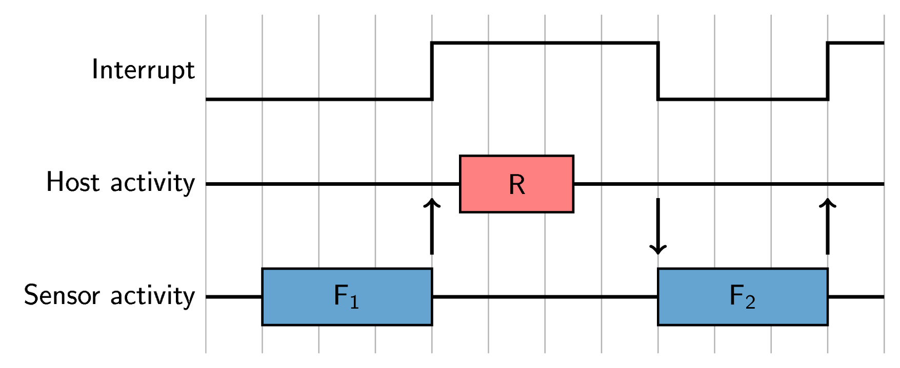
In the basic way of operating the A121, the process goes through 3 repeating stages:
Measure: The host signals the sensor to start measuring. The interrupt pin will go low, and then high again when the sensor completes the measurement.
Wait for interrupt: The host waits for the interrupt indicating that said measurement is finished.
Read: The host reads out the data from said measurement.
Figure 12 below shows this operation.

Figure 12 Illustration of basic control flow of the A121. The top part shows the interrupt pin. The middle part shows what the host is doing, where a red box denoted with an R is a read. The bottom part shows what the sensor is doing, where a blue box denoted with a F is a frame measurement. A down arrow shows a measure call, and an up arrow shows a completed measurement.#
Note that in the case shown in Figure 12,
the rate of frame measurements is effectively given by the rate of the measure call.
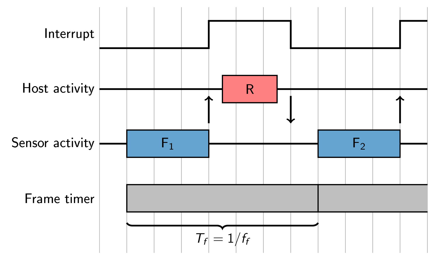
The A121 is also capable of triggering itself,
giving an extremely accurate rate.
This is done by setting the frame_rate in configuration.
In this case, the sensor will not start its measurement until the corresponding time has passed.
Figure 13 shows this method of operation.

Figure 13 Illustration of a control flow of the A121 where the frame rate is set. For context, see Figure 12. The bottom part shows the frame timer set up according to the frame rate.#
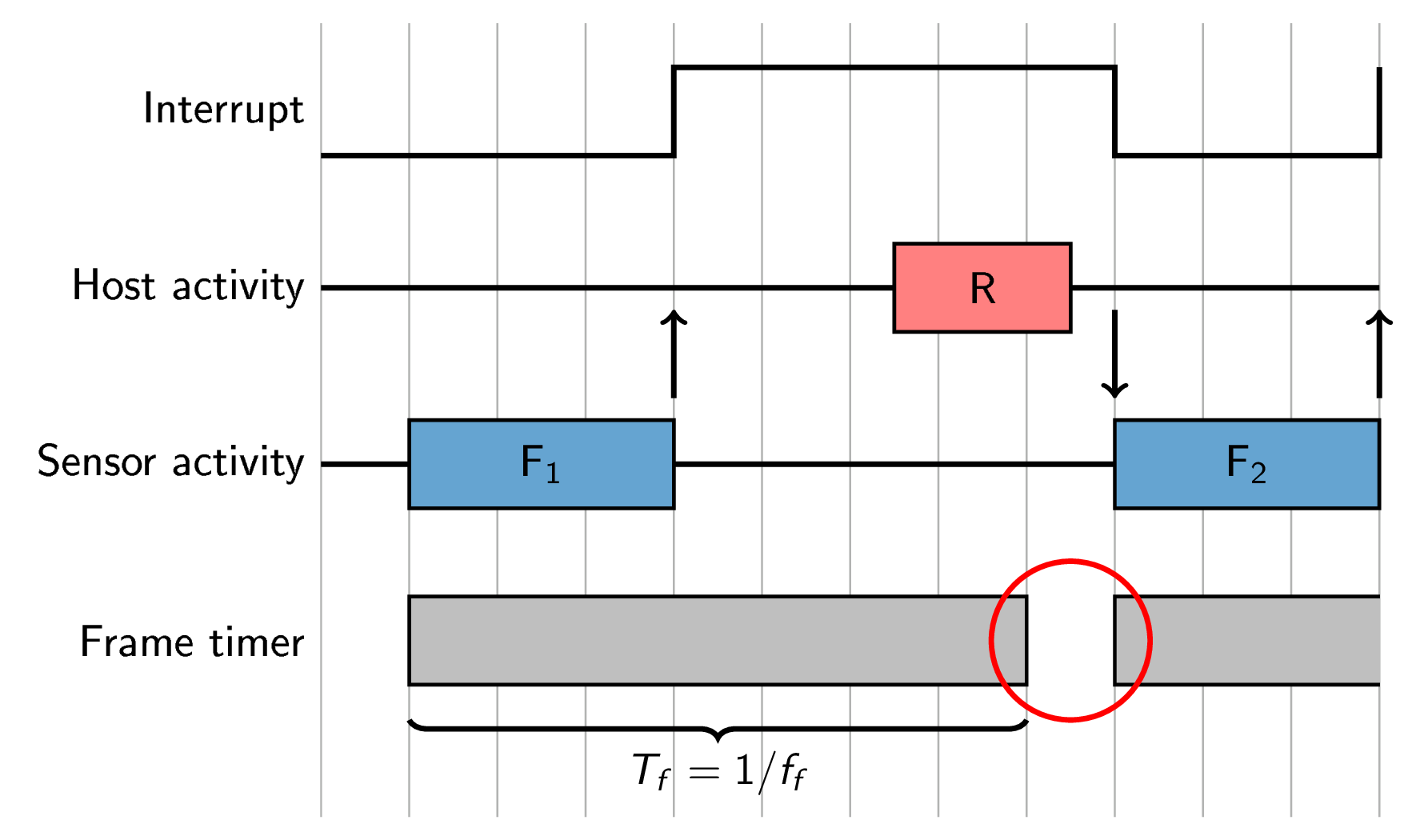
In the case shown in Figure 13, we can see that the measure call, making the interrupt go low, happens before the timer ends (which triggers the frame measurement start). If the host responds with the call after the timer ends, the frame measurement will be delayed, as illustrated in Figure 14 below.

Figure 14 Illustration of a control flow of the A121 where the frame rate is set and the host responds late. This makes the frame delayed. For context, see Figure 13.#
Double buffering#
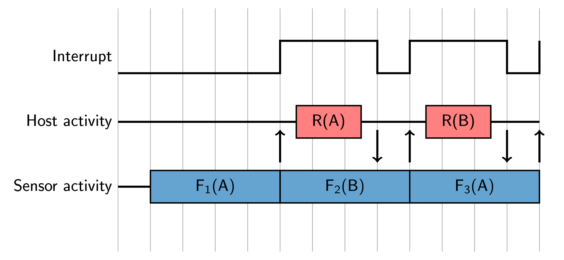
The A121 is capable of operating in a double buffering mode
where two data buffers (A & B) are used to be able to read out data and measure at the same time.
This feature is enabled by the configuration parameter
double_buffering.
Commonly used together with Continuous sweep mode (CSM).
Using this mode changes the control flow slightly,
in that the sensor will be one frame measurement ahead of the host at all times.
Other than that, the principles for rate control are the same.

Figure 15 Illustration of a control flow of the A121 using double buffering.#
Double buffering is typically used for one of two reasons:
Enabling Continuous sweep mode (CSM), where the sensor timing is set up to generate a continuous stream of sweeps.
Giving the host more time to read out the data before a subsequent frame measurement.