Profiles#
The first step is to select pulse length profile to optimize on either depth resolution or radar loop gain, or in terms of use cases, optimized for multiple objects/close range or for weak reflections/long range, respectively.
Depth resolution, \(d_{res}\), is the ability to resolve reflections which are closely spaced, and hence depends on \(t_{pulse}\) according to
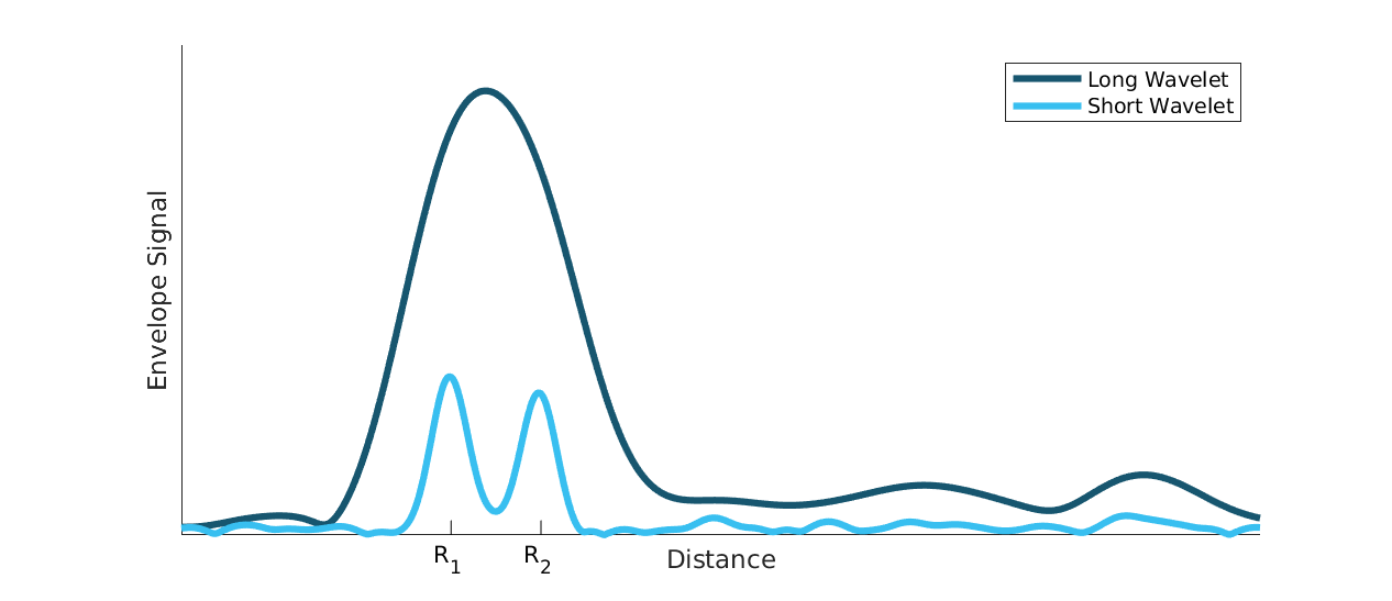
Figure 61 illustrates how the ability to resolve closely spaced reflections can be improved by decreasing \(t_{pulse}\). On the other hand, decreasing \(t_{pulse}\) means that the total energy in the pulse is decreased and hence decrease the SNR in the receiver, this is the trade-off that is made by selecting between the five profiles. Each service can be configured with five different pulse length profiles (see Table 19), where
shorter pulses provides higher distance resolution at the cost of a reduced SNR
longer pulses provides higher SNR at a cost of reduced depth resolution

Figure 61 Illustration of received signal containing 2 echoes. A longer pulse increases the radar loop gain, but also limits the depth resolution. The displayed data corresponds to the two setups in Figure 62.#

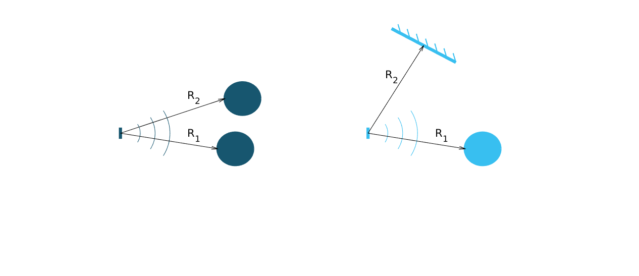
Figure 62 Illustration of scenarios that can produce the data in Figure 61. A strong reflector, such as a flat metallic surface, can give a moderate radar signal if the angle to the radar is high. \(R_1\) is identical in the two illustrations as well as \(R_2\).#
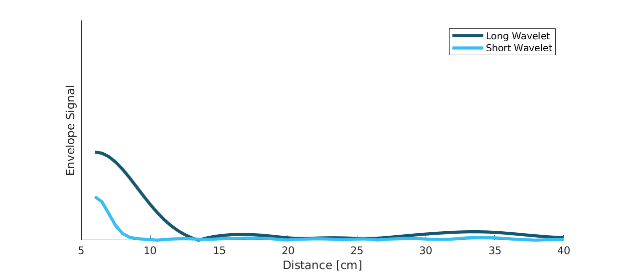
Optimizing on depth resolution also means that close-in range performance is improved. The A111 sensor has both the Tx and Rx antenna integrated and since they are so closely spaced, there will be leakage between the two antennas. This means that any object close to the sensor will have to be filtered from this static leakage. The ability to do this is improved if a short \(t_{pulse}\) is used, as illustrated in Figure 63.
If angular information is needed one possibility is to mechanically move the sensor to scan an area and produce a synthetic aperture radar (SAR). One such case is for autonomous robots using sensor input for navigation. Another option is to use multiple A111 sensors and merge data from them to calculate the position of the object by trilateration. This can be achieved by running the sensors sequentially and merge the data in the application.

Figure 63 Illustration of how the leakage between the Tx and Rx antenna will appear in the Envelope Service data for Profile 1 and Profile 2 pulse lengths.#
Profile |
Relative SNR improvement [dB] |
Direct leakage [m] |
|---|---|---|
Profile 1 |
0 |
~0.06 |
Profile 2 |
~7 |
~0.10 |
Profile 3 |
~11 |
~0.18 |
Profile 4 |
~13 |
~0.36 |
Profile 5 |
~16 |
~0.60 |