
How to configure#
Considerations#
Start by asking yourself the following questions related to your application:
What range do we need to cover, from \(r_\text{near}\) to \(r_\text{far}\)?
Do we need to distinguish multiple objects? If so, how close could they be?
Do we need to measure distance to objects? If so, what trueness is needed?
If objects move, how fast could they go?
Do we need to measure motions of objects? If so, at what speeds?
With what rate do we need to obtain a result?
What are our requirements on overall power consumption?
What is the farthest distance from the sensor that an object may appear which could result in range ambiguities?
Range-related parameters#
Having these questions and answers in mind, we go though the parameters in order, starting with those related to the range:
Use the highest profile possible for maximum overall power and time efficiency. It is often limited by \(r_\text{near}\) since the close-in distance (CID) must be smaller than \(r_\text{near}\), and higher profiles have a larger CID. If you need to resolve multiple objects, the duration of the pulse must be short enough to give the resolution needed. Finally, lower profiles may give more precise distance measurements.
The step length should be as long as possible to reduce memory usage and decrease measurement time. It is typically limited by two things:
Distance measurement trueness: As a rule of thumb, the steps need to be 1/10 to 1/2 of the required trueness. Note that as steps get smaller, other factors such as SNR and pulse duration (profile) have a bigger impact on the general accuracy.
The profile: If steps are too long, reflecting objects may fall between points, creating “blind spots” in the range. See Figure 22 for an example.
From here, the start point and number of points can be set. Just make sure the points cover \(r_\text{near}\) to \(r_\text{far}\). Due to the pulse length (profile), the start and end points does not necessarily have to pass \(r_\text{near}\) and \(r_\text{far}\). Again, see Figure 22 for an example of this. However, keep in mind that distance measurements typically cannot be done in the very edge of the range, so you might have to extend it outside \(r_\text{near}\) and \(r_\text{far}\) anyways.
Set the PRF such that the resulting maximum unambiguous range (MUR) extends beyond the farthest distance an object may appear. Keep it as high as possible since a higher PRF is more power and time efficient overall.
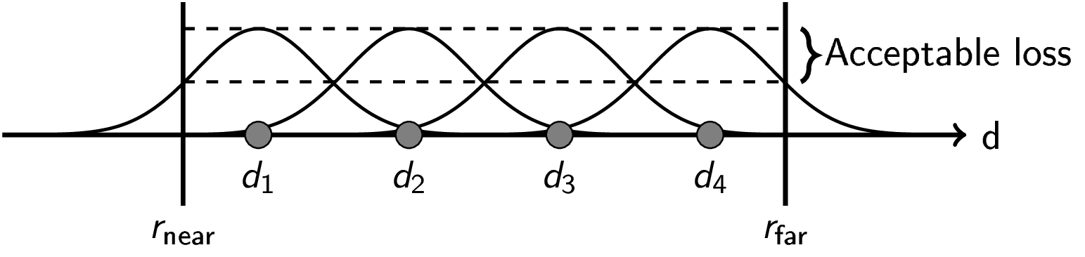
Figure 22 A sketch of setting up the measurement range for efficient coverage of a given area.#
Channel configuration#
The A212 has 3 transmitter (TX) and 4 receiver (RX) antennas. By selecting which antennas are active, the measurement is performed over a set of virtual channels, each corresponding to one active TX and RX antenna pair. The number of virtual channels is the product of the number of active TX and RX antennas. Activating all 3 TX and all 4 RX antennas gives 12 virtual channels, the maximum for the A212.
The active antennas are controlled per subsweep through two bit mask parameters:
tx antenna mask - selects active TX antennas. Bit 0 maps to TX0, bit 1 to TX1, bit 2 to TX2. Setting all three bits (
0b111 = 7) activates all TX antennas (default). At least one bit must be set.rx antenna mask - selects active RX antennas. Bit 0 maps to RX0, bit 1 to RX1, bit 2 to RX2, bit 3 to RX3. Setting all four bits (
0b1111 = 15) activates all RX antennas (default). At least one bit must be set.
Example 1: single channel (TX0 + RX0 only):
Set tx_antenna_mask = 0b001 = 1 (bit 0 set, TX0 active) and rx_antenna_mask = 0b0001 = 1 (bit 0 set, RX0 active).
This yields 1 × 1 = 1 virtual channel (TX0 and RX0 pair).
Example 2: six channels (TX0, TX1 with RX0, RX1, RX2):
Set tx_antenna_mask = 0b011 = 3 (bits 0 and 1 set, TX0 and TX1 active) and rx_antenna_mask = 0b0111 = 7 (bits 0, 1, and 2 set, RX0, RX1, and RX2 active).
This yields 2 × 3 = 6 virtual channels (all TX0/TX1 and RX0/RX1/RX2 pairs).
Different subsweeps within the same sensor configuration may use different antenna masks, allowing flexible multi-channel configurations within a single frame. See Frames, sweeps and subsweeps for details on how channels appear in the output data.
Other parameters#
Leave receiver gain at the default value and reduce if saturation occurs.
Leave enable TX set (default).
Leave jitter compensation enabled (default) for improved phase stability between sweeps. It occupies one of the five subsweep slots, so a configuration using all five has to disable it. Disable it also when the highest possible sweep rate is required.