
Frames, sweeps and subsweeps#
Frame layout#
The sparse IQ service may be configured to perform several sweeps at a time in a so-called frame. Thus, every frame received from the sensor consists of a number of sweeps. Every sweep in turn consists of a number of points spanning the configured distance range (see Measurement range).
Some examples of suitable applications for multiple sweeps per frame are detecting motions, measuring velocities, and tracking objects.
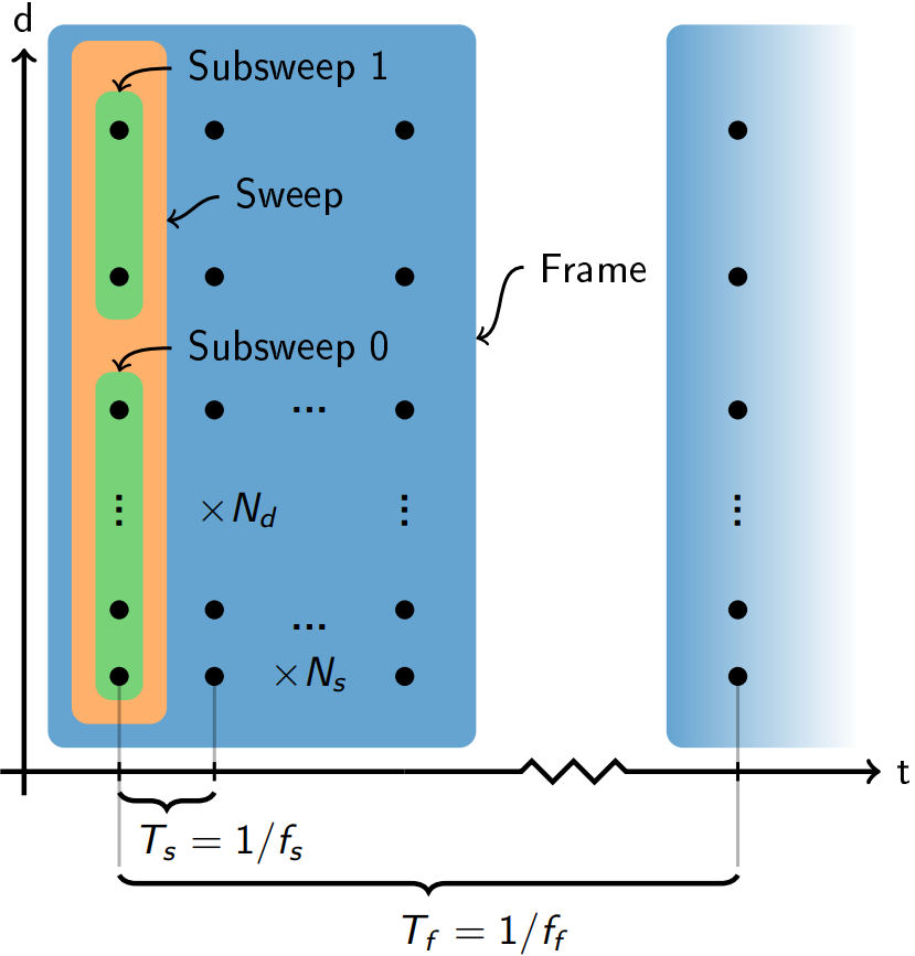
Figure 30 An illustration of the sweep and frame concept.#
As shown in Figure 30, \(N_s\) is the number of sweeps per frame (SPF). Typical values range from 1 to 64. The sweeps are sampled consecutively, where \(T_s\) is the time between two corresponding points in consecutive sweeps. This value is typically specified as the sweep rate \(f_s=1/T_s\). It is given by the sensor configuration, but is optionally limited to a fixed rate, letting the sensor idle between sweeps. Typical sweep rates range from 1 kHz to 10 kHz.
In a similar fashion as for sweeps, the frame rate is defined as \(f_f=1/T_f\). Typical values range from 1 Hz to 100 Hz. The sensor may idle in efficient low power states between frames, so maximizing the idle time between frames is crucial for minimizing the overall power consumption.
The timing of frames can be done in two ways – either by letting the host trigger measurements of new frames, or by letting the sensor itself trigger on a periodic timer.
Subsweeps#
The purpose of the subsweeps is to offer more flexibility when configuring the sparse IQ service. As the name implies, a subsweep represent a sub-region in the overall sweep. Each subsweep can be configured independently of other subsweeps, e.g. two subsweeps can be configured with overlapping range and different profiles.
Measurement execution order#
As previously discussed, a frame consists of one or more sweeps, which in turn can be divided into multiple subsweeps. The execution order is as follows:
The points are measured along the distances defined by start point, num points and step length.
If subsweeps are utilized, they are measured in the order defined by the sensor configuration.
After the measurement of the sweep (potentially containing subsweeps) is completed, the next sweep is measured.
This is repeated until sweeps per frame sweeps have been measured
Lastly the frame is formed by stacking the sweeps.
The following example illustrates the concept:
Assume a sensor configuration with three subsweeps and two sweeps per frame. Firstly, points are measured according to the distances specified by the first subsweep, followed by the measurements according to the second and third subsweep. Next, a second sweep is performed with the same subsweep configuration. Lastly, the two sweeps, containing three subsweeps, are stacked to form the frame.
TX and RX execution order#
For A212, the measurement execution order described above extends to multiple antennas within each subsweep. For each distance point, the sensor steps through the active TX antennas in the order TX0, TX1, TX2. For each TX transmission, all active RX antennas receive simultaneously, producing one IQ sample per RX antenna. This sequence is repeated for every distance point and every sweep in the frame.
Channel representation#
Each active TX and RX antenna pair forms one virtual channel. A frame therefore has three dimensions: sweeps, channels, and distance points, as illustrated below.
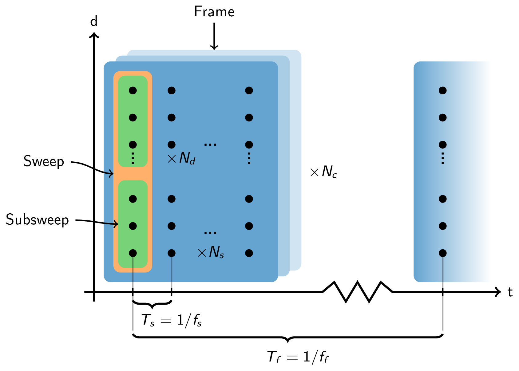
Figure 31 A frame contains \(N_s\) sweeps, each composed of one or more subsweeps (inner green bars) within a sweep envelope (outer orange bar). Data is collected for \(N_c\) virtual channels (stacked dimension) at \(N_d\) distance points per sweep.#
Channel numbering#
Channels are numbered in TX-major order:
where \(N_{RX} = 4\) is the total number of RX antennas on the A212.
With all antennas active (tx_antenna_mask = 0b111, rx_antenna_mask = 0b1111),
channels 0 through 11 are assigned as follows:
RX0 |
RX1 |
RX2 |
RX3 |
|
|---|---|---|---|---|
TX0 |
0 |
1 |
2 |
3 |
TX1 |
4 |
5 |
6 |
7 |
TX2 |
8 |
9 |
10 |
11 |
When only a subset of antennas is active, only the corresponding channel numbers appear.
For example, with tx_antenna_mask = 0b101 (TX0 and TX2), channels 4-7 are absent and
the active channel numbers are 0-3 and 8-11.
Frame data layout#
Result exposes frame data as a 2D array of shape
(sweeps_per_frame, columns_per_sweep), where columns_per_sweep is the concatenation
of all subsweeps of \(\text{num\_points} \times \text{num\_channels}\).
Within each subsweep block of columns, data is arranged point by point. For each distance point, all active channels are stored consecutively in TX-major order:
subsweep 0 columns:
[ pt0_ch0, pt0_ch1, ..., pt0_ch(N-1), pt1_ch0, ..., pt(M-1)_ch(N-1) ]

subsweep 1 columns (if present):
[ pt0_ch0, ... ]
where M is num_points and N is the number of active channels for that subsweep,
and channel indices are TX-major within the active set.
Use get_subframe() to extract the data for a specific
subsweep as a (sweeps_per_frame, num_points * num_channels) array.
Pass channel_indexes to select a subset of channels by TX-major channel index.
See also
How to configure for antenna mask configuration and channel count.
Limitations#
Unlike A121, A212 does not have a fixed frame buffer that caps the total number of IQ samples. The frame buffer is allocated dynamically in host SRAM, so the practical upper bound depends on available memory on the host platform.
The individual parameters are bounded as follows:
sweeps per frame: 1 to 512.
subsweeps: 1 to 5 per sensor configuration. When jitter compensation is enabled it takes one of the slots, leaving 4 for the application.
num points: 1 to 65535 per subsweep.
virtual channels: 1 to 12 per subsweep (up to 3 TX times up to 4 RX).
The total frame data in bytes is \(\text{sweeps\_per\_frame} \times \sum_{\text{ss}} (\text{num\_points}_{\text{ss}} \times \text{num\_channels}_{\text{ss}}) \times 4\).