
Measurement range#
Sweep range#
The sparse IQ service can be configured to measure practically any range of distances in a so-called sweep. In other words, a sweep makes up the points in space where reflected pulses are measured.
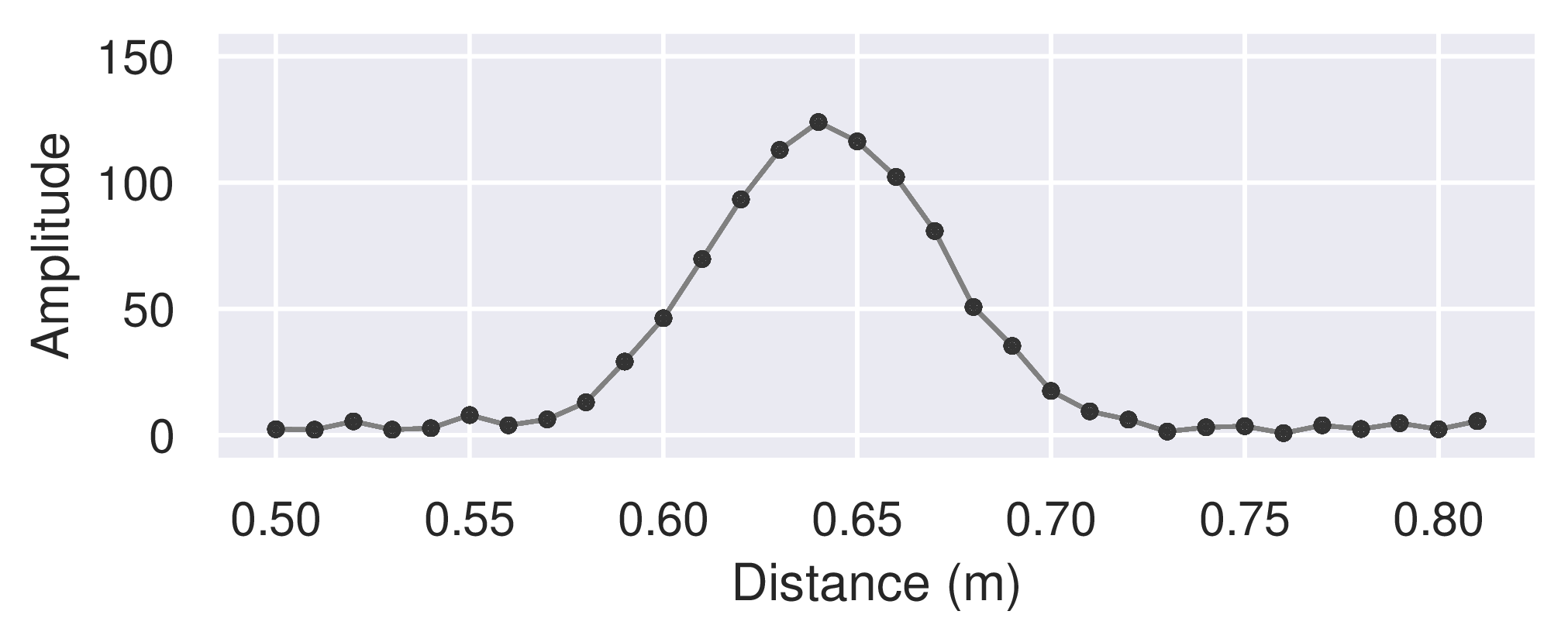
Figure 28 Amplitude of a mocked sweep of an environment with a single object.#
Figure 28 above shows an example of a sweep with a range spanning from a start point at ~ 0.50 m to an end point at ~ 0.81 m. Here, a total of 32 points were measured with a distance between them of ~ 10 mm, also configurable. The shortest configurable distance between points is ~ 2.5 mm.
The more points that are measured, the more memory is used and the longer it takes to measure the sweep. This may in turn lead to higher overall duty cycle and power consumption. Thus, it is often important to try to minimize the number of points measured, typically achieved by maximizing the distance between the points.
Configuration#
For preciseness, the range is configured in a discrete scale with three integer parameters – the start point \(d_1\), the number of points \(N_d\), and the step length \(\Delta d\). The step length corresponds to the distance between the points (mentioned above). The distance between the points in the discrete scale is ~ 2.5 mm, which is also why the shortest configurable distance between points is just that.
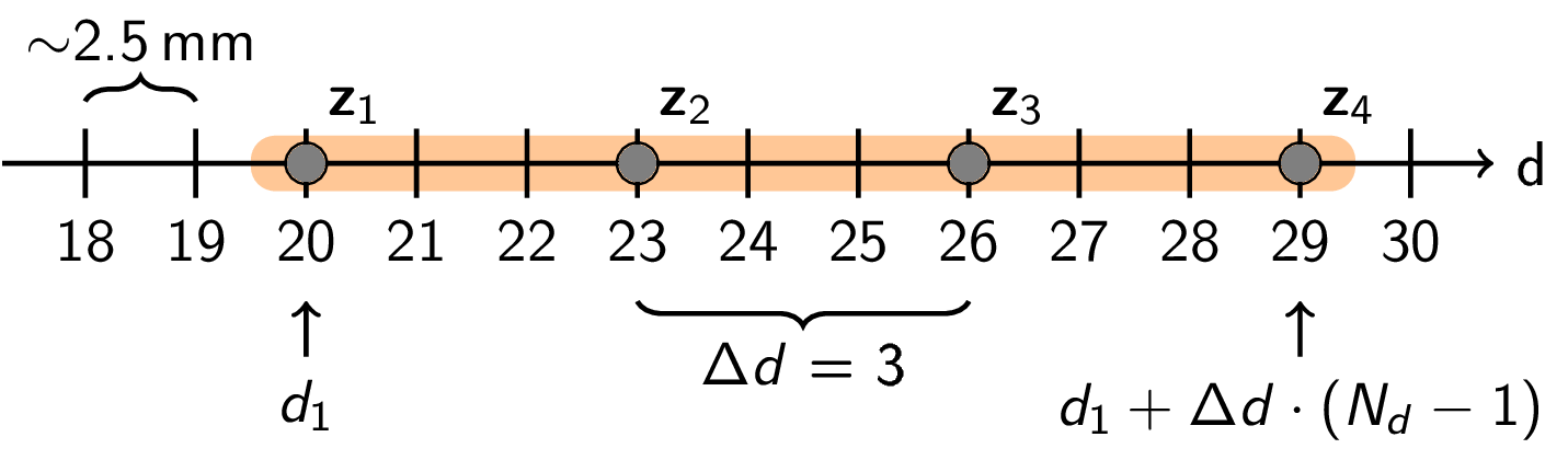
Figure 29 An illustration of the sweep range concept.#
Figure 29 above demonstrates how a range can be set up with these parameters. The start point \(d_1=20\), the number of points \(N_d=4\), and the step length \(\Delta d = 3\) This gives the discrete points \(\{20, 23, 26, 29\}\) which correspond to \(\{50.0 mm, 57.5 mm, 65.0 mm, 72.5 mm\}\).
Note that the possible values for step length \(\Delta d\) are limited.
Caveats#
A number of factors affect the actual real world distance of a given range point:
The refractive index and thickness of materials the radar signal pass through.
Systematic errors due to process, supply voltage, and temperature variations.
Reference clock frequency.
Step length#
The base distance between measurement points is approximately 2.5 mm when step length \(\Delta d = 1\). The step length can be set to any integer from 1 to 3072, giving a maximum inter-point spacing of approximately 7.7 m. In practice, step lengths rarely exceed a few hundred, as larger spacings would cause most targets to fall between measurement points.
Pulse repetition frequency#
The maximum measurable distance (MMD), i.e., the farthest configurable end point, and the maximum unambiguous range (MUR) depend on the pulse repetition frequency (PRF). The lower the PRF, the longer the MMD and MUR, as listed in Table 9.
PRF setting |
PRF |
MMD |
MUR |
|---|---|---|---|
|
27.7 MHz |
2.4 m |
5.4 m |
|
20.8 MHz |
4.2 m |
7.2 m |
|
15.8 MHz |
6.6 m |
9.6 m |
|
12.5 MHz |
9.0 m |
12.0 m |
|
8.3 MHz |
15.0 m |
18.0 m |
|
5.3 MHz |
25.0 m |
28.0 m |
The default PRF is PRF_20_8_MHZ, giving an MMD of 4.2 m.
Objects located beyond the MUR may fold back into the measured range.
For example, with PRF_20_8_MHZ (MUR 7.2 m), an object at 8.0 m could appear at
\(8.0 - 7.2 = 0.8\) m.
See also
PRF for the complete enumeration of PRF values.