Radome and mechanical design#
A radome is the product housing or plastic cover in front of the radar that protects it from mechanical impact and weather, see Figure 60. When designed correctly, the radome is effectively transparent to the radar signal and thus not impacting the radiated performance.
Transmission and reflection#
When an electromagnetic (EM) wave hits the interface between two dielectrics, such as plastic and air, reflection and refraction occur at the boundary. Inside the dielectric, the propagation speed and wavelength change depending on the material’s permittivity. If the wavelength in free space is \(\lambda_{0}\), 5 mm at 60 GHz, the wavelength inside the material is \(\lambda=\frac{\lambda_{0}}{\sqrt{\varepsilon_r}}\), where \(\varepsilon_r\) is the relative dielectric constant of the material.
In the case of linearly polarized propagation at normal incidence, the Fresnel equations relate the ratio between the incident and transmitted fields:
where \(Z_{1}\) and \(Z_{2}\) are the corresponding wave impedances. The transmission and reflection factors are also related by \(t = 1 + r\). In most cases, we have non-magnetic materials so that \(Z = \sqrt{\frac{\mu_{r}}{\varepsilon_r}} = \frac{1}{\sqrt{\varepsilon_r}}\). An important special case is normal incidence between air and a dielectric. The reflection coefficient then simplifies to
From this expression, we can see that the materials with a higher dielectric constant produce stronger reflections of the incidence signal. Conductors, such as metal, have a very high dielectric constant (\(\varepsilon_r \rightarrow \infty\)) and thus produce a strong reflection. Most polymers have a dielectric constant in the range 2–4, and therefore give a weaker reflection.
Radomes#
Radome thickness#
Let \(d_1\) be the distance to the radome, \(d_2\) the thickness, \(r_1\) and \(r_2\) the reflection coefficients, and \(t_1\) and \(t_2\) the corresponding transmission coefficients according to Figure 60. As an incident wave hits the first interface, a reflection \(r_1\), and a transmission \(t_1\) occur. Note that \(r_1 < 1\), so the reflected wave is out of phase with the incident wave. At the second interface, another reflection \(r_2\) and transmission \(t_2\) take place. With air on both sides of the dielectric, note from Eq. 27 that \(r_1 = -r_2\). The total reflection coefficient \(\Gamma_1\) then becomes [1]:
where \(k = 2\pi/\lambda\) is the wave number in the material. Two notable special cases follow:
For \(d_{2} = m\frac{\lambda}{2}, \; m = 1,2,...\) we have \(e^{-2jk d_{2}}=1\) and \(\Gamma_{1} = 0\).
For \(d_{2} = m\frac{\lambda}{4}, \; m = 1,3,5,...\) we have \(e^{-2jk d_{2}}=-1\) and \(\Gamma_{1} = \frac{2r_{1}}{1+r_{1}^{2}}\).
The optimum radome thickness occurs when the dielectric is perfectly reflectionless, i.e. when the thickness is a multiple of half a wavelength. This can also be understood from the fact that the round trip of the wave inside the radome introduces a 360° phase shift, thereby cancelling the reflected wave \(r_{1}\).

Figure 60 Transmitted and reflected signals from a half-wavelength radome. Secondary reflections have been omitted for simplicity.#
As an example, if the material is polycarbonate (PC) with relative permittivity \(\varepsilon_r=2.75\), the optimal radome thickness becomes:
If the dielectric thickness is an odd multiple of \(\frac{\lambda}{4}\), maximum reflection occurs. The relative dielectric constant of some more materials can be found in Table 18.
Radome distance#
In addition to radome thickness, the distance between the sensor and the radome also affects performance. Depending on the radome thickness and distance, the initial reflection from the radome will cause multiple reflections between the sensor, PCB, and radome. This leads to a standing-wave pattern where the amplitude varies as a function of radome distance. The amplitude variation will be minimal if the reflected wave from the radome is in phase with the transmitted wave. The optimum radome distance is
Figure Figure 61 shows the measured amplitude variations of the reflected wave from a radar target when the distance between the sensor and the radome is varied for different radome thicknesses. The radome has a dielectric constant of \(\varepsilon_r=2.6\), so the optimum thickness is \(d_{2} = 1.55 \approx 1.6 \:\mathrm{mm}\), which shows the minimum amplitude variation. When the radome thickness is a multiple of \(\frac{\lambda}{4} = \frac{3.1}{4} \approx 0.7 \:\mathrm{mm}\), the maximum amplitude variation is observed as a function of distance.
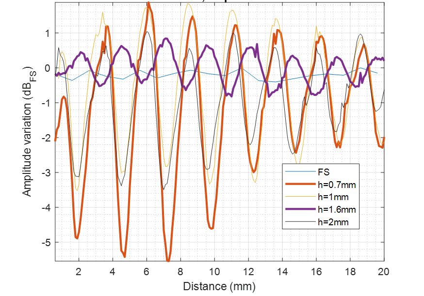
Figure 61 Amplitude vs. radome thickness and distance. Amplitude variation is shown for a single direction (Tx or Rx). For combined Tx+Rx, the values are doubled.#
If absolute distance measurements are required for a particular use case, an additional offset should be applied. This offset compensates for the propagation delay introduced by the radome. It can be determined through reference measurements, and also allows the reference plane to be positioned at the desired location within the product. For multi-layer radome optimization, see [1].
Dielectric constant of common materials#
The dielectric constant of some common polymers at 60 GHz is presented in Table 18.
Material |
Re(\(\varepsilon\)) at 60 GHz |
|---|---|
Acrylic glass |
2.5 |
Alumina |
9.3 |
Fused Quartz |
3.8 |
MACOR |
5.5 |
PEEK |
3.12 [3] |
PMMA |
2.6 [4] |
Polycarbonate (PC) |
|
Polyethylene (PE) |
|
Polypropylene (PP) |
|
Polystyrene (Rexolite) |
2.5 |
PTFE (Teflon) |
2.05 [5] |
Footnotes